| Version 2 (modified by mark1, 17 years ago) (diff) |
|---|
Lidar Processing Protocol
- Copy data onto windows machine
- Process the navigation (IPAS and GrafNav)
Check roll vs time graph in IPAS (stick in ticket for future reference) Check PDOP and Combined Separation Iterate until we get the best trajectory we can
- Process the LIDAR using the finalised calibration parameters
In the case of images that exhibit roll offsets AFTER application of the boresight parameters then apply the following procedure:
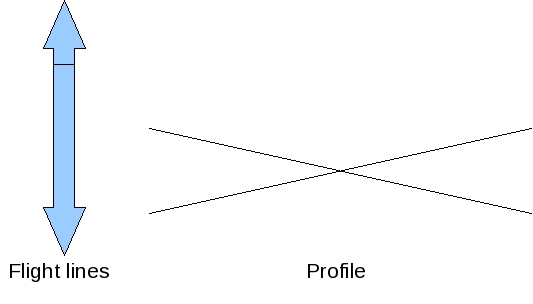
- A) Opposing flight lines (fully overlapping)
- Can observe profiles across track ideally for an area of flat terrain for each pair of images and manually tweak the roll values to remove bias
- Record the final “tweaks” in file XYZW
- B)Parallel flight lines (semi-overlap, all same direction)
- Using overlap region for each pair of images can manually tweak roll until bias removed
- Record the final “tweaks” in file XYZW
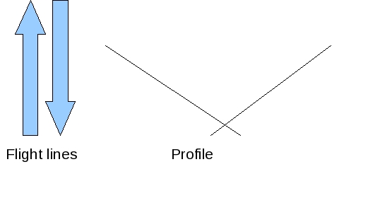
- C) Parallel flight lines (semi-overlap, opposing direction)
- Look for zig zagging elevations on all flight lines eg /\/\/\ (beware of true sloping terrain)
- tweak roll manually until flight lines look more like ------
- Record the final “tweaks” in file XYZW
- D) Non overlapping flightlines
- If we have a roll offset model (produced by analyzing the tweaks and other info noted in A to C above) that we know corrects the data then use this
- Else deliver as is informing PI there is possible (probable) bias in the data, and give an estimate of the magnitude if possible.
For each image in each data set note the following:
- Calibration file used
- Flight height and direction
- Roll correction used
- Approx position (in E/N?)
- Time (from take off) of start of acquisition
- Collate the data and analyse it – look for trends within the flight data sets (per project) and also the complete set of data (all projects together).
Attachments (3)
-
oppose.jpg
(24.4 KB) -
added by mark1 17 years ago.
Opposing flight lines
-
paralell_same.jpg
(22.0 KB) -
added by mark1 17 years ago.
Parallel same direction flight lines
-
paralell_diffjpg.jpg
(22.2 KB) -
added by mark1 17 years ago.
Parallel different direction flight lines
Download all attachments as: .zip