| Version 9 (modified by benj, 16 years ago) (diff) |
|---|
Choosing an appropriate pixel size
Quick reckoner
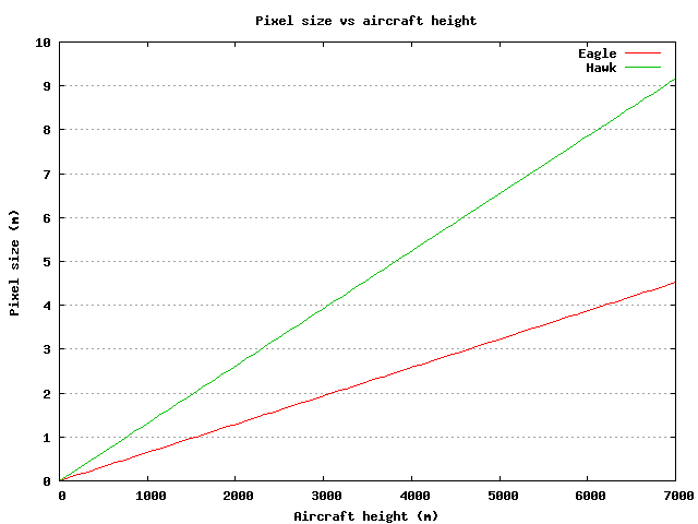
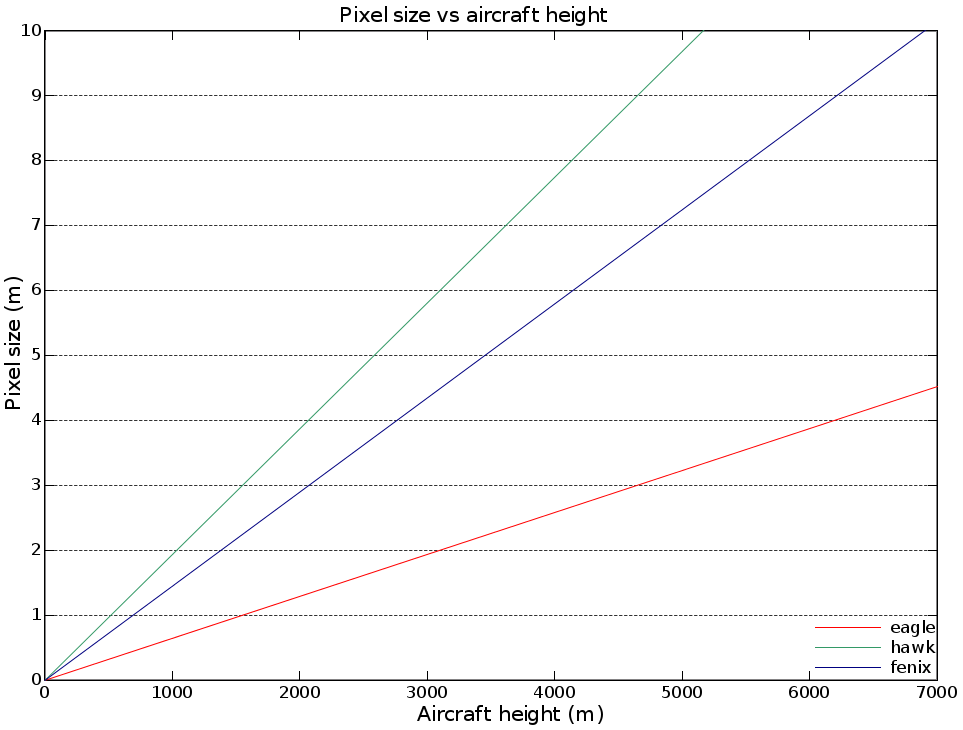
This graph gives the theoretical pixel size at nadir for Eagle and Hawk. Pixel size will be larger at the edges of the swath, so at least to start with you should use a slightly higher value than that given by this graph. Also note that this is primarily across-track pixel size, along-track will vary with the speed of the aircraft. We suggest that most users should use square pixels based on the across-track pixel size, but see the note below regarding along-track pixel sizes.
This javascript calculator will give the exact value for pixel size given an altitude using the formula from the graph below
![]()
Note this is the altitude over the ground, not the altitude from GPS (which is over the spheroid and takes no account of local terrain variation).
The along-track IFOV is the same as the across-track one for Hawk, and is either 2.5 (for datasets with spatial binning 1, ie most of them) or 1.25 (for datasets with spatial binning 2) times the IFOV for Eagle. This means that the along-track pixel size scales by that much relative to the across-track size. However, the along-track pixel size is also affected by the aircraft speed and the integration time used, so for high speeds or long integration times you may find you need to use longer pixels.
Logsheets provided by ARSF contain the altitude from GPS. One must compensate for the average terrain height when using the reckoner above. For example, if your data is over coast areas and thus at sea level, the numbers are fine as is. If your data is over a mountain valley, one should subtract the average height of the terrain from the logsheet altitude, then use that ground-altitude in the table above.
azgcorr-based pixel size
To get a (still approximate) "best" pixel size, run through azgcorr once and there's a block in the azgcorr output:
Pixel spacing stats... along line...
  centre     min: 3.67 max: 3.79 ave: 3.74
  port       min: 3.01 max: 18.31 ave: 8.50
  starboard  min: 1.20 max: 14.58 ave: 5.08
  across line centre (pix 256): 3.68
You need to pick a pixel size that is close to the "across line centre" value, but smaller if the terrain is high up and larger if you get a lot of tearing of the image at the edges.
Best pixel size procedure
To get the best pixel size, start with a large pixel size (5 or 10m) and process just a few bands for speed.
Reduce the pixel size progressively until you stop getting more detail out of the smaller pixel sizes or the edges start tearing.
If you find that you're getting tearing at the edges but you still want to make the pixel size smaller to increase detail, you can also increase the interpolation value used by azgcorr - use the -g flag, which takes two values, eg: azgcorr ... -g 5 5. Azgcorr automatically interpolates across any dropped frame gap smaller than the first number times the pixel size, and the second number determines how many successive data frames must be available before it will consider that a gap has ended (default 4 4 - about 10m for 2.5m pixels). Be aware that because this is interpolation, increasing this number does not necessarily improve your data in the gap, but just how it looks.
Along-track pixel size tables
These tables were provided by Bill Mockridge and give calculated effective pixel sizes in the along-track direction for a variety of different combinations of conditions. In general we recommend using square pixels for ease of processing and of data visualisation, but if you prefer to use non-square pixels then look at these tables.
Sensor specific notes
As regards pixel size, the largest effect is the movement of the aircraft during image acquisition. All sensors take some time per scan accumulating light and, during this time, the aircraft will move forwards.
- ATM is a scanning sensor, so the aircraft will move forwards as the scan proceeds, resulting in a 'tilted' scan. This is accounted for in the processing.
- The effect on CCD sensors is that pixels will be longer along-track than across-track
- Additionally, the Specim instruments have pixels that are inherently non-square (along track) due to the design of the slit.
Detailed email from Bill on pixel sizes:
Level 1 pixel "size" would be the dimensions of the solid view vector
from the sensor to the intersection with the ground. So although you
have a pixel FOV it's in radians. The actual ground sizes required the
navigation and DEM to convert this to metres on the ground. The table
listed from the nav pre-processing part of azgcorr only uses the
position info not the sensor parameters. These are made use of in the
calculation of pixel coordinates, and there is no listing from that
section of the program.

So in a way, if one is pedantic,  "Pixel spacing stats" is a misnomer -
it perhaps should be retitled: "Scan ends and centre spacing"!. Also,
throughout, "line" is the flight line and across line would be scan
direction but you have to allow for the heading - track ie drift angle.
Also for the ATM (rotating mirror scanner)  the scan will not be a
straight line as it takes a time to acquire during which the aircraft
will have moved and CCD instruments have the integration period to take
into account, so they can end up looking at long streaks in the along
flight line direction; at typical flight speeds the plane does 6cm per
msec, so if the integration is 30msec  you have got 1.8 m motion
already! It's even more complicated because the Eagle and Hawk appear to
have an along line IFOV twice as large as the across line. I can let you
have a table of pixel dimensions at different heights, speeds and
integration if you are interested.

The spacing is referring to that of the scans, projected to spheroid
using the aircraft spheroid height as given by the gps, ie they do not
take into account the DEM. Think of a view triangle from the sensor to
the ground, where the apex angle is the total field of view, the sides
are the peripheral view vectors and the base side is approximately the
projection on the spheroid of the scan; the height of the apex is the
aircraft height above the spheroid.

So centre, port and starboard refer to the distance apart from one scan
to the next of the ends and centre of the scans after 3D transformation
using the attitude and aircraft 3D position. The "across line centre"
size is obtained by using the centre pixel instantaneous field of view
and the average flight height for the line; again above the spheroid; so
in a way is a more representative size than the scan spacing.

This is not intended to be actual pixel size on the ground as that would
need to be obtained after using the DEM, if present. This is only meant
as a guide to choose an output pixel size. Because of this one would use
a pixel size close to the "across line centre"; but you would reduce the
size if the ground was high or increase the size if the averages at the
scan edges show a lot of attitude opening of the scans.

You have to also remember that the area viewed by a single pixel is not
a clear cut-off; the pixel's point spread function is assumed to be
gaussian, so it "sees" into the surrounding ones.
Attachments (3)
-
pixelsize.png
(4.4 KB) -
added by benj 16 years ago.
'Ideal' pixel size vs. aircraft height for Eagle and Hawk
-
pixelsizegraph.2.png
(2.7 MB) -
added by stgo 12 years ago.
'Ideal' pixel size vs. aircraft height for Eagle Hawk and Fenix
-
pixelsizegraph.png
(2.7 MB) -
added by stgo 12 years ago.
'Ideal' pixel size vs. aircraft height for Eagle Hawk and Fenix