| Version 5 (modified by adbe, 14 years ago) (diff) |
|---|
Hawk Bad Pixel Generation
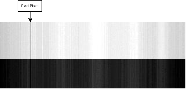
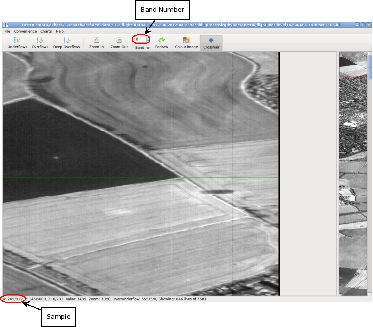
The Hawk sensor contains bad pixels which are usually constant throughout the whole season, so during the calibration of Hawk bad pixels are identified and are used later in apl to mask/interpolate over bad pixels. Here is an example of a bad pixel present in the calibration data set:
![]()
During calibration of the hawk sensor a noise and linearity measurement should have been taken, to identify these files look in the final capture spreadsheet under ~arsf/arsf_data/YEAR/misc/CAL_DAY, the entries that are used for the bad pixel generation are listed with a "Noise & Linearity" measurement. The files should be something like: NO1H1113, and have an integration time listed in the row; there may be some with a blue filter these can also be used in the detection of bad pixels.
There are 5 detection methods for finding a bad pixel:
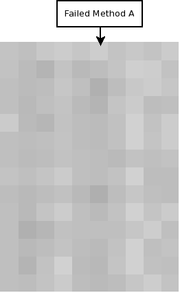
Method A
Constant Light Inconstant Response
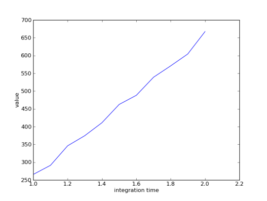
During the calibration the hawk sensor receives light from an integrating sphere, this produces constant stable light, therefore if a pixels response varies then this pixel is considered bad. For example:

The calculate whether a pixel is bad get the mean for the light region of the pixel, if a member of this pixel is less or greater than a given percentage it is considered bad.
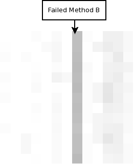
Method B
Deviation From Spectral And Spatial Neighbours
Attachments (5)
-
bad_pixel_example.png
(39.3 KB) -
added by adbe 14 years ago.
bad pixel example
-
method_A_example.png
(3.1 KB) -
added by adbe 14 years ago.
method A example
-
method_B_example.png
(2.7 KB) -
added by adbe 14 years ago.
method B example
-
method_C_example.png
(18.7 KB) -
added by adbe 14 years ago.
method C example
-
method_E_example.png
(310.6 KB) -
added by adbe 14 years ago.
method E example
Download all attachments as: .zip