| Version 11 (modified by stgo, 11 years ago) (diff) |
|---|
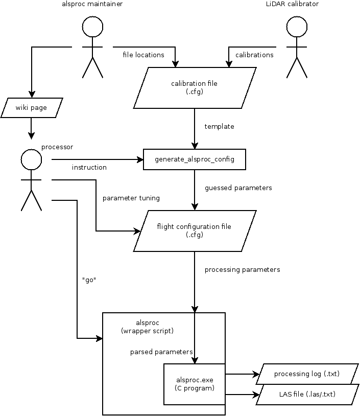
Overview
This guide describes how to process LiDAR data using alsproc and the ALS Post Processor
Alsproc can either be run locally using alsproc_batch.py (linked as just alsproc) or on the grid using alsproc_submit.py. Note that presently it will only run correctly on fedora 19 machines and as such you must submit to the development grid. Check with someone on how to do this, you'll need to update SGE_CELL.
Configure
The configuration file is made with the generate_alsproc_config.py program. It will examine your current working directory and derive a project directory, from which it will determine the best available calibration to base your configuration file on, and populate it with information derived from your flightlines. This can take a while, as it needs to perform a cursory check on all of the raw data.
This presently only works on fedora 19 machines.
generate_alsproc_config
Example:
airborne@pmpc1322:/users/rsg/arsf/arsf_data/2013/flight_data/uk/RG12_09-2013_121_Wessex# generate_alsproc_config
Gathering details about project...
Using calibration file (/users/rsg/arsf/calibration/lidar/20130219/als50.cfg)...
Collating details for .cfg file...
Writing .cfg file
Scanning flightline 130501_093511... ok
Scanning flightline 130501_094820... ok
Scanning flightline 130501_100234... ok
Scanning flightline 130501_101637... ok
Scanning flightline 130501_102953... ok
Scanning flightline 130501_104304... ok
Scanning flightline 130501_105631... ok
Scanning flightline 130501_113351... ok
Scanning flightline 130501_114825... ok
Scanning flightline 130501_120434... ok
Scanning flightline 130501_121952... ok
Scanning flightline 130501_123433... ok
Scanning flightline 130501_125655... not ok, check failed on duration
all done
Flightlines which alsproc thinks it might not be able to process based on this check will be flagged here, as in the case of the last flightline, and not be marked to be processed.
Next, edit the .cfg file created. If you did not specify, it will be under processing/als50/*.cfg.
Fields of particular interest to you as a data processor are:
- output-format - can normally be left as the default
- output-projection - will need to be set per-flight depending on where the flight is based, consult the projections table below
- output_dir - default is probably fine, but it can be useful to change, especially when working on the pitch and roll values later
- sol-file - change this to the location of the sol file created during navigation processing, it may already be filled in for you
- sup-file - as with the sol file
| Projection | Use-Case | output-projection |
| British National Grid | all British flights | ukbng |
| UTM | everywhere else | utm zone=<zone number> hemisphere=<n/s> hrz_datum=wgs84 vrt_datum=wgs84 |
- UTM zones need to be selected appropriately, a map of UTM zones can be found here: http://www.dmap.co.uk/utmworld.htm
You may also change the output formatter from the standard LiDAR formatter. The following table lists the options and values you should enter in each field.
| Format | Use-Case | output-format | output-file-ext (recommended) |
| las (default) | normal processing | las12_las | .las |
| ascii | experimental/analytical reasons | txt | .txt |
It is likely that there will be a pitch/roll offset as described below. Correcting this works in a similar manner to hyperspectral SCT correction. You will need to add the following fields to the cfg file to iterate over a range of pitch/roll/heading corrections:
#roll-correct = -0.0035000
roll-start = -0.0030000
roll-end = -0.0040000
roll-inc = -0.0001
This would result in 11 las files being created, each at a 0.0001 increment. Switch out roll for pitch or heading if you need to process those. You need to comment out or remove the -correct value or alsproc will not run.
Note that you can only run one of pitch/roll/heading as incrementing at present, this is to stop confusing files but could be added in if it is felt it is needed.
Be certain about your -inc value as this can result in very large numbers of files being produced.?
You will then see a section for each flightline. process_line should be set to true for each flightline unless there was some problem, in which case the maintainer for alsproc should be contacted.
[110618_090736]
output-file = %(output_dir)s/ldr110618_090736%(output-file-ext)s
process_line = true
line_number = 1

# GMT 09:07:52 to 09:08:39, 47.3 seconds
start-time = 1640,551272.000006
end-time = 1640,551319.282274
delta-avg-diff = 0.000006667852
scanner-fov = 18.932618
scan-rate = 58.214212
multi-pulse = false
Generate
Alsproc is fed its arguments with the wrapper script alsproc_batch.py, which also handles certain LiDAR preformatting if using las12_las.
alsproc processing/als50/2013121.cfg
Log files will be kept for each flightline in the directory specified by log_dir in the configuration file, for your use if alsproc should suffer from some processing error.
Pitch and Roll Errors
First you will need to generate an initial dataset to base some observations off
airborne@pmpc1322:/users/rsg/arsf/arsf_data/2013/flight_data/uk/GB13_05-2013_144_Glenmore/processing/als50# generate_alsproc_config
Gathering details about project...
Using calibration file (/users/rsg/arsf/calibration/lidar/20130219/als50.cfg)...
Collating details for .cfg file...
Writing .cfg file
Scanning flightline 130524_130407... ok
Scanning flightline 130524_130807... ok
Scanning flightline 130524_131239... ok
Scanning flightline 130524_131711... ok
Scanning flightline 130524_132140... ok
Scanning flightline 130524_132606... ok
Scanning flightline 130524_133035... ok
Scanning flightline 130524_133540... ok
Scanning flightline 130524_134001... ok
Scanning flightline 130524_134447... ok
Scanning flightline 130524_134927... ok
Scanning flightline 130524_135443... ok
Scanning flightline 130524_135900... ok
Scanning flightline 130524_140340... ok
Scanning flightline 130524_140918... ok
Scanning flightline 130524_141340... ok
Scanning flightline 130524_141645... ok
Scanning flightline 130524_142158... ok
Scanning flightline 130524_142738... ok
all done
Then edit the resulting .cfg file and set the appropriate fields. Example:
output-projection = +init=epsg:27700 +nadgrids=/users/rsg/arsf/usr/share/proj/OSTN02_NTv2.gsb +geoidgrids=/users/rsg/arsf/usr/share/proj/osgm02_wgs.gtx
sol-file = %(project_dir)s/posatt/ipas_honeywell/proc/20130524_103914.sol
sup-file = %(project_dir)s/posatt/ipas_honeywell/proc/20130524_103914.sup
output-projection is set according to global position. This is a UK flight so I have selected the British National Grid.
sol-file and sup-file have been set according to what was created during the navigation processing.
Then process the dataset. This can take a while; 20 minutes to 20 hours depending on the size of the dataset and load on the network. On early iterations, you may identify just a few flightlines and focus your efforts on those, but you must check flightlines from across the entire dataset, as pitch and roll has been known to change over the course of a flight in the most unfortunate cases.
alsproc 2013144.cfg
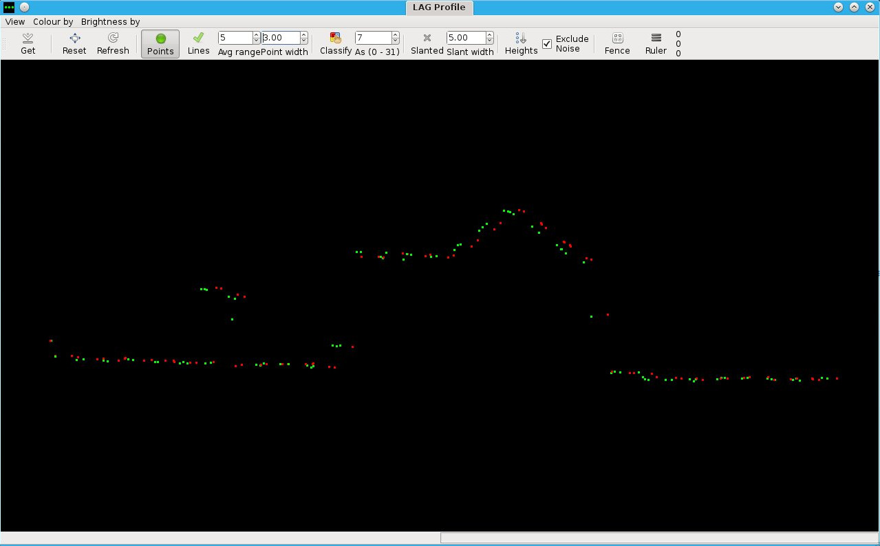
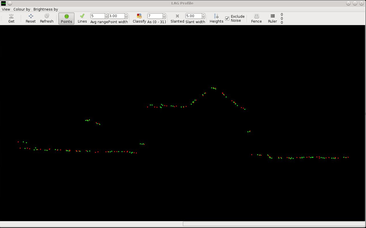
Then go into the dataset and look for rooftops or other features both along and across areas of overlap. It should look like this:

Using the ruler tool come up with the best possible approximate for lateral displacement both along and across the overlap. Normally this will be in the region of 50cm to 10cm. If the displacement is less than 5cm or 10cm in both directions then the files you have should be ok to use and you can use the pitch and roll errors you used for this attempt in your final solution. If not, you will need to estimate some new pitch and roll errors and try again. An example of acceptable pitch and roll errors is given below.

Determine the direction of your error. You need to decide whether to add or subtract from each of the pitch and roll error in the fields pitch-correct and roll-correct respectively. Look at the times of a few points in each flightline to determine each of their directions, and then decide whether you want to roll the angle of the laser clockwise or anticlockwise around the direction of travel of the plane to move the data left or right respectively; and whether you want to pitch up or down to move the data forwards or backwards respectively.
The table below indicates the effects of addition of subtraction on each axis.
| Operation | Pitch | Roll |
| addition | backwards | left |
| subtraction | forwards | right |
You may estimate the magnitude of your adjustment yourself based on your own intuition or previous observations if you wish. Using an equation can help you zero in on the correct solution more quickly, especially in your first two or so observations.
e = arctan( d / (h1 + h2) )
Where: e will be your error to add to or subtract from the value used to compute this dataset, d is the difference you measured in lag, h1 and h2 are the heights of the plane in each flightline above the terrain at the time of the observation. (Make sure you convert everything to the same units of measurement, such as metres.)
Now return to processing the dataset, you can inspect the data and pass it off, or you can perform another iteration to get the match even closer. The number of iterations you will need to do can vary, but often depends on the quality of the navigation data.
Attachments (3)
- workflow_diagram.png (28.1 KB) - added by besm 12 years ago.
-
pitch_error_249-2012.jpg
(65.1 KB) -
added by besm 12 years ago.
pitch error shown
-
pitch_error_corrected_249-2012.jpg
(57.7 KB) -
added by besm 12 years ago.
pitch error corrected
Download all attachments as: .zip