| Version 8 (modified by mark1, 13 years ago) (diff) |
|---|
Instrument Boresighting
When fitted in the aircraft the remote sensing instruments do not have a prefect nadir pointing direction. Typically this will be off by a small amount (a fraction of degree) in 3 degrees of freedom. This angular offset needs to be calculated to get precise geocorrection and positioning on the ground. To show the importance of this, for example, if there is an error of 0.5 degrees in the view vector, at an altitude of 1000m this could lead to an error of about 10m at the swath edge.
Every time the instruments are placed in the aircraft a new boresight flight has to be undertaken over the calibration site. This may just be at the start of the flying season or multiple times throughout the year. At the end of the flying season a boresight flight is undertaken to check if any change has occurred.
A list of boresight values used by ARSF-DAN can be viewed here.
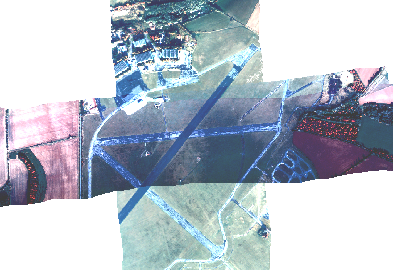
Hyperspectral Boresight Procedure

Flight requirements:
- Multiple flight lines taken along different flight paths
- Opposite and overlapping: e.g. 1 line North and 1 line South
- Parallel and overlapping: e.g. 2 lines East
- A third direction: e.g. NorthEast
Typically we collect fully overlapping flight lines going along the compass directions: N, NE, E, SE, S, SW, W, NW
Processing technique:
The first stage of the processing is to remove possible timing offsets due to the navigation synchronisation problems. This is because an along track shift occurs as consequence of the timing error and needs to be resolved first.
When these timing offsets have been identified the boresight procedure can begin. This is currently a case of processing the data with different boresight values (given in roll, pitch and heading angular offsets) and finding a set which appears to minimise location errors for all the flight lines.
As a good starting point it is useful to use the opposite flight direction flight lines to solve for roll and pitch. As a roll error will manifest itself as an across track shift and a pitch error as an along track shift. Be wary though that heading errors will also appear as a mixture of across and along track shifts. Heading errors are best identified using parallel lines with a 50% along track overlap.
LiDAR Boresight Procedure
Flight requirements:
- Multiple flight lines taken along different flight paths at different altitudes
- Opposite and overlapping: e.g. a line North and a line South
- Parallel and overlapping: e.g. 2 lines East
- Ideally 4 or 5 lines each from at least 2 or 3 altitudes: 750m, 1350m, 2200m
Typically we will collect 11 or 12 lines going N, S, E and W taken at different altitudes.
Processing technique:
The boresighting procedure for the LiDAR is similar to the hyperspectral instrument boresighting, except that we also have the z (height) error to help identify the offsets. It is often the case that errors are identified easier by examining vertical profiles of overlapping data as well as horizontal ones.
The angles (pitch, roll and heading) that describe the pointing direction of the laser scanner with respect to the nadir need to be identified along with the 'pitch error slope'. The pitch error slope is an error term that describes the fact that the mirror is not mounted perfectly flat against the laser. Therefore as the mirror moves the pitch of the beam will change by a small amount. The resulting errors are along-track offsets just like the pitch errors, but varying, with no error at nadir and maximum error at the edges of the swath.
To correct for the pitch offset we take opposing flight lines. If there is a pitch error then the lidar will be sensing pulses ahead/behind (along track) of the nadir point. There will be a small overall range error, but the main effect will be that the data is shifted backwards/forwards of where it should be.
If there is a small roll error, surfaces will be tilted up on one side of the swath and down on the other. In opposing flight lines, these errors will be on different sides of the swath. Vertical displacements due to roll error will be most noticeable at the edges of the swath. For small errors, the nadir point will be roughly the same, for large ones, there will be some across-track shift, but that will be much harder to measure than the vertical errors.
If there is a heading error, one side of the swath will appear further ahead (along track) of the other side. Looking at opposing flights will not help with this but overlapping, parallel lines will (where the overlap is ~30-50% across the swath). Examining the overlapping region will show an along track shift if there is a heading error.
Note that typically the LiDAR range corrections will be identified during the same procedure, and so using the z errors to identify the boresight means an iterative approach to this is required. This is coming soon: for now see Processing/LidarCalibrationProcedure
Attachments (1)
-
boresight_cross.png
(1.0 MB) -
added by mark1 14 years ago.
Boresight NSEW Cross lines
Download all attachments as: .zip