| Version 15 (modified by mark1, 17 years ago) (diff) |
|---|
Calibration of the Leica ALS50 II LIDAR
This page describes the procedure for calibrating the ARSF LIDAR. The procedure is performed in 3 main stages: Boresight, Range correction and validation. For full information on the calibration see here.
Boresight
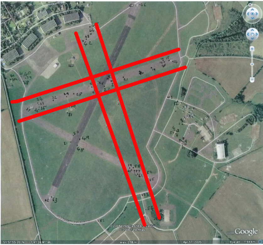
The first stage of calibrating the LIDAR is to calculate the boresight angles. These are the angles in pitch, roll and heading that describe the pointing direction of the laser scanner with respect to the nadir. Using incorrect boresight parameters will result in georeferencing errors and gross errors will be obvious when comparing overlapping flight lines, especially lines flown in varying directions. The boresight calibration is performed using data taken at 3 altitudes: 750m, 1350m and 2300m. The flight lines are acquired in 'cross formations' and parallel lines with a sizeable overlap.
Pitch
To correct pitch we take opposing flight lines. If there is a pitch error, the lidar will be sensing pulses ahead/behind (along track) the nadir point. There will be a small overall range error, but the main effect will be that the data is shifted backwards/forwards of where it should be.
Roll
If there is a small roll error, surfaces will be tilted up on one side of the swath and down on the other. In opposing lines, these errors will be on different sides. Vertical displacements due to roll error will be most noticeable at the edges of the swath. For small errors, the nadir point will be roughly the same, for large ones, there will be some across-track shift, but that will be much harder to measure than the vertical errors.
Heading / Yaw
If there is a heading error, the left side of swath will move backwards while the right side will move forwards (or vice versa). If you reverse the direction of flight (ie. with opposing flight lines), these errors will overlap (left side down in one direction matches right side up in the other) and not be visible. Instead, take two parallel flight lines with 30-50% overlap
Pitch error slope
The mirror will not be mounted exactly flat to the laser so, as the mirror moves, the pitch of the beam will change by a small amount. The resulting errors are along-track offsets just like the pitch errors, but varying, with no error at nadir and maximum error at the edges of the swath.
Procedure
The main procedure in the boresight correction is:
- Process Navigation
- Process raw scan to attune files in ALS Post Processor
- Use Attune to calculate boresight parameters
- Analyse in Terrascan - reprocess if necessary
- Process the Navigation as per usual using IPAS Pro and Grafnav
- In ALS Post Processor:
- uncheck the “average last returns” option in the settings dialog
- Check the output as attune files in the outputs dialog
- Add all the flight data into the ALSPP, including the BIT mode data.
- Run the Rangecardcal program from the utilities menu. Select the use all SCN files option when prompted.
- Enter range offset A1 as 0 since it is unknown#
- Enter the output Range offsets into the range corrections dialog of ALSPP. Only need R1 for A and B for now.
- Uncheck the BIT mode data (we don't need to process this) and run the ALSPP processing
- Look at the filesizes of the output data. If the ATN.LAS files are over 400MB in size then Attune will not run. If this is the case re-process with only the part of interest of the line.
- Part of interest will be the area where all flight lines overlap.
- Ground classification needs to be performed on the files before tie pointing in Attune. But to load the ATN.LAS files into Terrascan we need to first import them into Attune to convert them. To do this we need to start the Attune software
- We do this so that we only use points on the ground in the tie pointing (since we don't want errors due to perspective or shadowing)
- In Attune - Add ALS data -> add the real ATN.LAS files from the ALSPP output
- The suggested pixel sizes (from top level calibration pdf) are 0.3m for 750m, 0.4m for 1350m and 0.8m for 2300m.
- View the image pngs to make sure no data holes. (Some are OK. Re-load using a different resolution if too many holes. e.g. Try 0.35m for 750m)
- 'a' centres the image
- '+/-' to zoom in/zoom out
- There should now be some files with .bin extension. These can be imported into Terrascan for ground classification.
- Ground classification procedures can be found here
- Once the data have been ground classified re-start Attune and tie point the data
- Now select tie points. We use streets for tie points since these should be on the ground so no (little) effects due to look angles and also has slow varying topography
- Open tie point editor in Attune.
- Press 'm' to measure a point and then click where you want it. Do this for each image (selecting the same point). Then press 'sample all' to record the locations.
- To change one, re-measure it and then just click 'sample point'.
- See this for hints on how to select tie points and improve location accuracy.
- Save the project after selecting 50-100 points. (Attune is very crash-able, save often)
- Select points on roads with uniform intensity. Use lines of roads and field boundaries to get the same place in each image. Don't use buildings as markers due to perspective/shadow.
- Edit project file properties.
- Torsion constant =-100,000
- Image observation Weights 0.2, 0.2, 0.1
- Atmosphere same parameters as in the ALSPP processing
- Set class as ground = 2 (ground is usually class 2)
- Adjustment criteria maxiter=50, angular (?)=1.00e-08
- Click Solve Calibration parameters and unselect Torsion, just want to solve roll, pitch and heading.
- Analyse adjustment
- A good result would have aposteriori reference of between 1 and 2.
- No. of observations of 300 is good
- Standard deviations of around 0.00001 for Roll and Pitch, 0.00005 for Heading.
- Average residuals of 25cm for X and Y, 5cm for Z is good.
- If the above criteria are not met (roughly...they are only guidelines)
- Analyse results and remove or adjust any points with large residuals
- Open all the images + point editor and then can select a point from the solution list and zoom to it on the images
- You could just remove the point from one or two images (especially the high altitude images) or from all images. Then recalculate the network adjustment and iterate until Aposteriori reference is approx 1-2 and average residuals are 0.25,0.25 and 0.05.
- Can remove the points from the lower resolution images if it will help. We want more measurements in the higher resolution images than the lower ones if they are unclear to measure in (so don't just measure in them for the sake of it)
- When happy save the solution - also note down roll, pitch and heading values in case of crashes
- Analyse results and remove or adjust any points with large residuals
- Now select tie points. We use streets for tie points since these should be on the ground so no (little) effects due to look angles and also has slow varying topography
- Return to ALS Post Processor
- Add the Pitch, Roll and Heading values into the boresight calibration dialog.
- Change output to LAS (not attune)
- Change output directory
- Re-run the processing
- Now analyse the results in Terrascan
- Check profiles etc for misaligning flightlines.
- To load all flightlines will probably need to use a fence (this is like a region of interest)
- To check the Roll accuracy – check opposing flights and look at cross sections at either end of the swath for a tilt (across track).
- To check the Pitch accuracy – check along track on slopes for offsets
- To check the Heading accuracy – check the parallel lines for offsets
- Also possible to check for errors by re-ordering points by elevation
- The boresight parameters can be manually twiddled (rather than using Attune) by reprocessing in ALS, changing the R,P,H values one at time. Only process parts of the flightlines for speed benefits.
- When happy with the results save the ALS Post Processor settings to a .reg file for future reference.
Range Calibration
The second stage in the calibration process is to calibrate the range offsets.
Can do range correction if the boresight results are good. This is a 2 stage process:
- 1. Nominal offset determination A1
- 2. Define relative differences for A2,A3,A4 and B1,B2,B3,B4
points have approx. the same range error within +/-7 degrees of Nadir, so we look only at this region firstly.
Procedure
- Start up ALS Post Processor
- In filters dialog set the angles to +7 and -7 degrees
- Change the output directory (to 02a_Roff+-7deg if using suggested directory structure)
- Run the processing on the 4 low altitude flight lines.
2.Load the results into Terrascan and use the 30-40 GCPs of the calibration site.
- GCPs are available here
- Tools -> Output Control Report
- Browse -> GCP file and remove bad points (maybe an error occurred in the surveying of a certain point)
- Look at the dz value, the average dz is used for the nominal range offset A1.
- Save the text file.
- Preferably using data including areas of forest and the BIT mode data, run Rangecardcal (from ALSPP tools menu)
- Enter the average dz value as A1 to get the other offsets.
- Add the outputs to the ALSPP dialog and save the settings reg file (to a new name)
- Analyse the results
- Check these results and re-run using the full FOV (~45 degrees)
- Check average dz is less than 1cm or so, and standard deviation <5cm in Terrascan control report. (also look at cross sections)
- Then process the 4 high altitude flights in ALSPP and check in Terrascan (around nadir and swath edges)
- Finally load in all flights into Terrascan (within a fence if memory issues) and check them (ideally along a stream because this has a “good” profile) Can use the travel path tool in Terrascan for comparing cross sections along a path.
Final validation
The final stage of the processing is tweaking the parameters and validating the calibration.
- Check the torsion and pitch slope
- To check the Torsion look at cross sections of high altitude cross flight. Flat roads and grassy areas are good. Look for “smiles” in the data. This can be done by looking at the centres of the edges of the overlapping area
- May also be able to do this by re-ordering points by elevation
- Save the final ALS PP options to a .reg file
Once finished
When the calibration has been completed and accepted, copy the reg files for each stage and the attune project files onto the Linux systems for backup. The final reg file should be copied to the arsf calibration repository and noted at the bottom of the wiki here
Attachments (1)
-
gcps-flightline.png
(890.5 KB) -
added by mggr 17 years ago.
Lil Riss cal site + GCP locations
Download all attachments as: .zip